| | Rhino 700 Electrical Problem - Solved! |  |
|
+5REDRHINO64 08Rhino450SE WV Hot Rod Rhino 123.bert0621 ChrisH 9 posters |
|
| Author | Message |
|---|
ChrisH

Posts : 475
Join date : 2013-03-10
Age : 42
Location : Texas (Victoria Area)
|  Subject: Re: Rhino 700 Electrical Problem - Solved! Subject: Re: Rhino 700 Electrical Problem - Solved!  Sun Sep 15, 2013 8:07 pm Sun Sep 15, 2013 8:07 pm | |
| Yes, I have a voltmeter. When my OEM grounds melted, I had to pretty much open the wire harness to assess and repair the wires. I remember that this ground (which also melted) connected inside the wiring harness. Could I attach a temporary wire with a ring terminal here back to the battery negative post?  | |
|
| | |
varmint10
Posts : 82
Join date : 2013-03-15
Location : Northern Calif.
| | Subject: Re: Rhino 700 Electrical Problem - Solved! Sun Sep 15, 2013 8:16 pm | |
| Yes hook a wire from there back to the battery negative terminal. Another thing to check is check battery voltage from the positive terminal to the negative terminal on the battery. Then check from the positive on battery and the negative connection in the picture. Check the two voltage and then make it fail and check the voltages when it fails, don't turn it off, just check these readings. | |
|
| | |
ChrisH
Posts : 475
Join date : 2013-03-10
Age : 42
Location : Texas (Victoria Area)
| | Subject: Re: Rhino 700 Electrical Problem - Solved! Sun Sep 15, 2013 8:30 pm | |
| Battery voltages with bad relay:
Battery (+) to (-) = 12.78
Battery (+) to relay (-) = 12.78 with key off
Battery (+) to relay (-) = 11.05 with key on [dash not illuminated]
Battery (+) to relay (-) = 0.46 with key on [dash illuminated normally]
Battery voltages with good relay:
Battery (+) to (-) = 12.81
Battery (+) to relay (-) = 12.81
Battery (+) to relay (-) = 0.04 with key on [dash illuminated normally] | |
|
| | |
varmint10
Posts : 82
Join date : 2013-03-15
Location : Northern Calif.
| | Subject: Re: Rhino 700 Electrical Problem - Solved! Sun Sep 15, 2013 8:35 pm | |
| Add the wire jumper. The ground is back feeding thru the relay, thats why it go to 0v when the dash is on.
The switches that you installed on your dash have lights right ? Unplug one of the ground wires going to it and jump from that wire to the battery negative. Make sure it is a ground wire.
Last edited by varmint10 on Sun Sep 15, 2013 8:38 pm; edited 1 time in total | |
|
| | |
ChrisH
Posts : 475
Join date : 2013-03-10
Age : 42
Location : Texas (Victoria Area)
| | Subject: Re: Rhino 700 Electrical Problem - Solved! Sun Sep 15, 2013 8:37 pm | |
| That is with the jumper.
I know the jumper is good because I get battery voltage from the battery (+) to the end of the jumper before connecting it to the battery (-). | |
|
| | |
varmint10
Posts : 82
Join date : 2013-03-15
Location : Northern Calif.
| | Subject: Re: Rhino 700 Electrical Problem - Solved! Sun Sep 15, 2013 8:39 pm | |
|
Last edited by varmint10 on Sun Sep 15, 2013 10:25 pm; edited 1 time in total | |
|
| | |
SteveS

Posts : 430
Join date : 2013-03-10
Age : 77
Location : Portland, OR
| | Subject: Re: Rhino 700 Electrical Problem - Solved! Sun Sep 15, 2013 9:42 pm | |
| - varmint10 wrote:
- I really believe it is the dash ground. The power relay is not failing because the coil is burning up. Somewhere there is a circuit that is letting current flow back thru it (bleeding) so everything works. But when the current demand is higher there is no path to ground. The power relay may even drop out because of insufficent current to stay energized. Find a place on the back of the dash to jump a wire directly to ground on the battery.
Do you have a volt meter ? I tend to agree that it is likely a grounding problem, but maybe differ on how to fix it. ChrisH had a major meltdown on the black ground wire string within the wire harness. As I understand it he had to unwrap a good portion of the wire harness to repair the junctions where branch wires are tied into the main runner. How that grounding scheme works on the Rhino is that there is a single wire connected to the battery negative that ties into every single ground return point in the electrical circuitry. It is daisy chained, in that the wire goes from one point to the next point and to the next point. There are also branches that come off of the main runner and connect to a ground point and perhaps then daisy chain onto yet another point(s). So, you can see that it is a horribly complicated mess to find a bad connection(s) in that string. Since the chassis is now reliably grounded via the cables going to the battery and to the engine case, I propose that those ground en-points be individually tied to a reliable chassis ground, while leaving the original grounding wire intact. You can imagine that this maze of ground wires has one or many failed or flakey junctions. As you go through and independently ground each point needing a ground, you will 'heal' the section of the harness that was not properly tied in, and any other ground points that are a member of that well interconnected segment will be 'healed' as well. ChrisH, I propose that you start with the points that are most likely directly involved with the main symptoms. These will all be black wires coming out of the wire harness. First one: The mains power relay has a black wire coming off of one side of the coil; ground that point to the frame. Second one: The headlight relay also has a black wire coming off the coil; ground that point to the frame. You can probably daisy chain your frame ground wire between these first 2 points (?). Third one: Ground the black wires coming out of the headlight connectors to the frame. Then fire it up and see what happened. My thinking is that you keep doing this until all problems go away...... | |
|
| | |
ChrisH
Posts : 475
Join date : 2013-03-10
Age : 42
Location : Texas (Victoria Area)
| | Subject: Re: Rhino 700 Electrical Problem - Solved! Sun Sep 15, 2013 10:10 pm | |
| - varmint10 wrote:
- Call me xxx-xxx-xxxx
Hey, thanks for the help! I'm not trying to avoid you. I got busy right after that last reply. - SteveS wrote:
- I tend to agree that it is likely a grounding problem, but maybe differ on how to fix it. ChrisH had a major meltdown on the black ground wire string within the wire harness. As I understand it he had to unwrap a good portion of the wire harness to repair the junctions where branch wires are tied into the main runner.
How that grounding scheme works on the Rhino is that there is a single wire connected to the battery negative that ties into every single ground return point in the electrical circuitry. It is daisy chained, in that the wire goes from one point to the next point and to the next point. There are also branches that come off of the main runner and connect to a ground point and perhaps then daisy chain onto yet another point(s). So, you can see that it is a horribly complicated mess to find a bad connection(s) in that string.
Since the chassis is now reliably grounded via the cables going to the battery and to the engine case, I propose that those ground en-points be individually tied to a reliable chassis ground, while leaving the original grounding wire intact. You can imagine that this maze of ground wires has one or many failed or flakey junctions. As you go through and independently ground each point needing a ground, you will 'heal' the section of the harness that was not properly tied in, and any other ground points that are a member of that well interconnected segment will be 'healed' as well.
ChrisH, I propose that you start with the points that are most likely directly involved with the main symptoms. These will all be black wires coming out of the wire harness. First one: The mains power relay has a black wire coming off of one side of the coil; ground that point to the frame. Second one: The headlight relay also has a black wire coming off the coil; ground that point to the frame. You can probably daisy chain your frame ground wire between these first 2 points (?). Third one: Ground the black wires coming out of the headlight connectors to the frame.
Then fire it up and see what happened. My thinking is that you keep doing this until all problems go away...... Thank you, also for your help. I want to try some of your suggestions. | |
|
| | |
123.bert0621

Posts : 1464
Join date : 2013-03-18
Age : 64
Location : Western Quebec
| | Subject: Re: Rhino 700 Electrical Problem - Solved! Sun Sep 15, 2013 10:12 pm | |
| Sounds like a bad ground, like Varmint says. | |
|
| | |
rhino727

Posts : 1317
Join date : 2013-03-25
Age : 59
Location : musella,Ga.
| | Subject: Re: Rhino 700 Electrical Problem - Solved! Sun Sep 15, 2013 10:21 pm | |
| good luck Chris , sounds like some good info , I do hate chasing a short hell I hate all wiring problems  | |
|
| | |
123.bert0621
Posts : 1464
Join date : 2013-03-18
Age : 64
Location : Western Quebec
| | Subject: Re: Rhino 700 Electrical Problem - Solved! Sun Sep 15, 2013 10:41 pm | |
| When your checking any wiring for continuity you should load test it, one strand of wire can give you battery voltage but cannot deliver the amperage to do any work. | |
|
| | |
SteveS
Posts : 430
Join date : 2013-03-10
Age : 77
Location : Portland, OR
| | Subject: Re: Rhino 700 Electrical Problem - Solved! Sun Sep 15, 2013 11:03 pm | |
| - varmint10 wrote:
- Yes hook a wire from there back to the battery negative terminal. Another thing to check is check battery voltage from the positive terminal to the negative terminal on the battery. Then check from the positive on battery and the negative connection in the picture. Check the two voltage and then make it fail and check the voltages when it fails, don't turn it off, just check these readings.
- ChrisH wrote:
- Battery voltages with bad relay:
Battery (+) to (-) = 12.78
Battery (+) to relay (-) = 12.78 with key off
Battery (+) to relay (-) = 11.05 with key on [dash not illuminated]
Battery (+) to relay (-) = 0.46 with key on [dash illuminated normally]
Battery voltages with good relay:
Battery (+) to (-) = 12.81
Battery (+) to relay (-) = 12.81
Battery (+) to relay (-) = 0.04 with key on [dash illuminated normally] I was re-reading this thread and realized that I had missed this portion of the conversation. Goes to show you that slow typists often miss out on the juicy stuff! I am unclear about exactly what the second point is that is being measured: " Then check from the positive on battery and the negative connection in the picture ". Or, as Chris writes in his listing: " Battery (+) to relay (-) ". Is this essentially the voltage measured across the relay contacts? | |
|
| | |
ChrisH
Posts : 475
Join date : 2013-03-10
Age : 42
Location : Texas (Victoria Area)
| | Subject: Re: Rhino 700 Electrical Problem - Solved! Sun Sep 15, 2013 11:06 pm | |
| I was measuring the red lead of my voltmeter to the battery positive terminal. The black lead of my voltmeter was at the large brown wire spade connector which plugs into the bottom of the relay. Did I measure the wrong thing? EDIT: this one 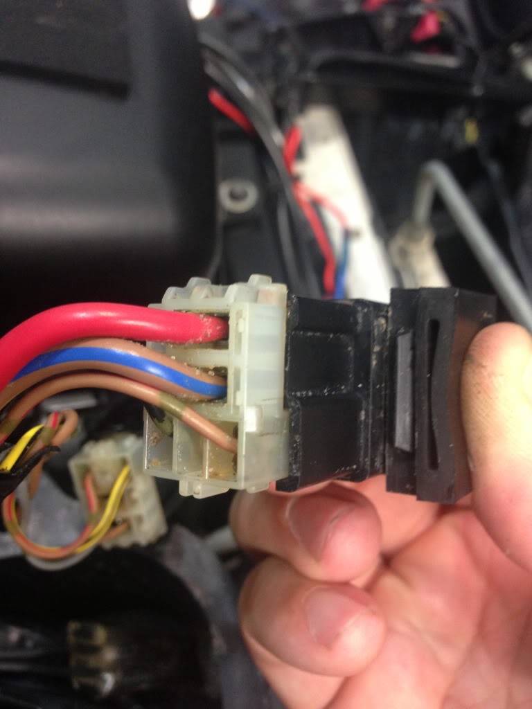 | |
|
| | |
varmint10
Posts : 82
Join date : 2013-03-15
Location : Northern Calif.
| | Subject: Re: Rhino 700 Electrical Problem - Solved! Sun Sep 15, 2013 11:15 pm | |
| - ChrisH wrote:
- I was measuring the red lead of my voltmeter to the battery positive terminal. The black lead of my voltmeter was at the large brown wire spade connector which plugs into the bottom of the relay.
Did I measure the wrong thing?
EDIT: this one
I was hoping you would read from the battery to the terminal you showed in the picture on the regulator. Did you ever try adding a ground wire to one of the lights on your switches? | |
|
| | |
SteveS
Posts : 430
Join date : 2013-03-10
Age : 77
Location : Portland, OR
| | Subject: Re: Rhino 700 Electrical Problem - Solved! Sun Sep 15, 2013 11:32 pm | |
| - ChrisH wrote:
- I was measuring the red lead of my voltmeter to the battery positive terminal. The black lead of my voltmeter was at the large brown wire spade connector which plugs into the bottom of the relay.
Did I measure the wrong thing?
EDIT: this one
OK, you are measuring the voltage across the relay contacts. When the contacts are open you should see a high voltage and when the contacts are closed you should see very low voltage. Essentially, when the contacts are closed you are measuring the voltage drop across the relay and the wiring going to the battery. Any appreciable voltage there when the contacts are closed is probably showing a high resistance between the relay contacts (contact corrosion, 'burning' or erosion). The numbers you see on the 'bad' relay are consistent with burnt contacts, usually from overloading the relay. If the bad relay is the one that you opened up, look at the contact surfaces with a magnifying glass. They should not be pitted and burnt up looking, like worn out ignition points in an old style automobile ignition system. This is good info. We need to figure out why though. This could just be collateral damage, if the relay coil does not pass enough current (low voltage across the coil) to tightly close the contacts, it might be causing arcing in the contacts. You sure have a doozy here :-) | |
|
| | |
ChrisH
Posts : 475
Join date : 2013-03-10
Age : 42
Location : Texas (Victoria Area)
| | Subject: Re: Rhino 700 Electrical Problem - Solved! Mon Sep 16, 2013 3:13 am | |
| I decided to try something. Maybe I do have a questionable ground somewhere in the harness. I can tell you that the relay that's giving me headaches is called the "load control relay" on the Yamaha wiring diagram. I want to try adding an additional ground to this relay. Here's what I ended up trying.  Soldered a 16AWG wire on to the harness ground wire. 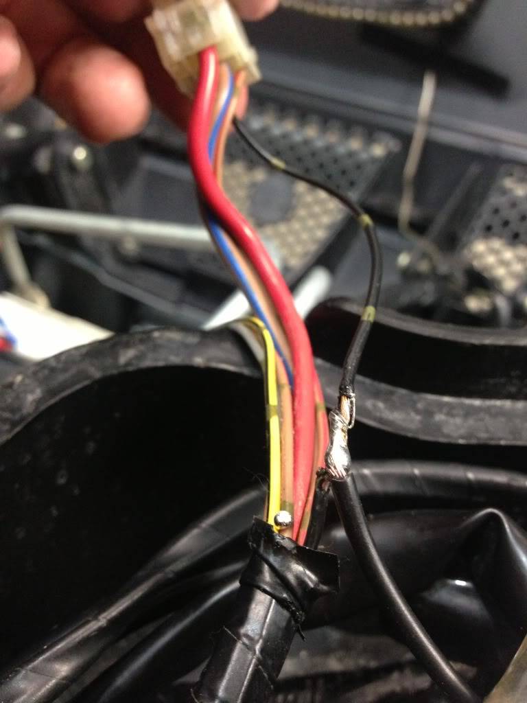 And I tied this back into my grounding strip for all my aftermarket accessories. This ground block is tied directly to the battery negative terminal. 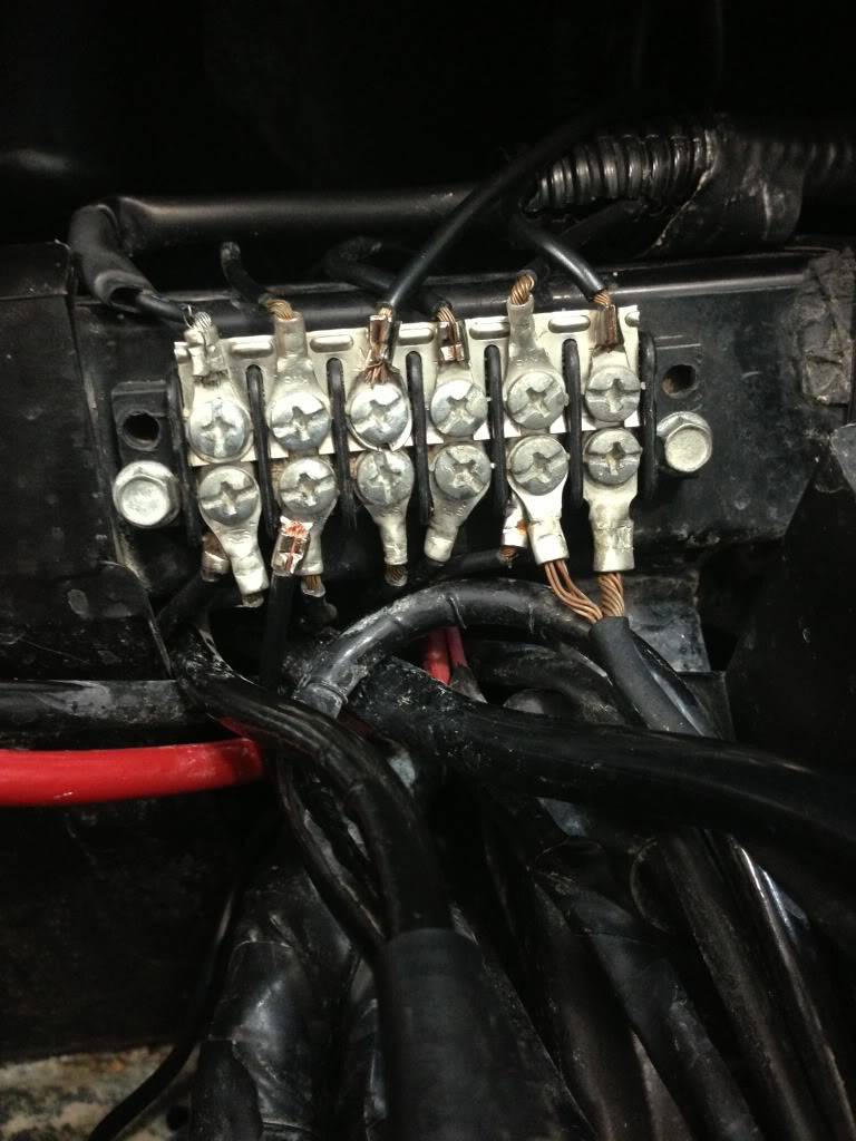 See, I told you that you shouldn't tie into the factory wiring. But I'm the one over here with electrical problems. Haha! I'm 99% sure my Rhino was built on July 5, national hangover day... | |
|
| | |
123.bert0621
Posts : 1464
Join date : 2013-03-18
Age : 64
Location : Western Quebec
| | Subject: Re: Rhino 700 Electrical Problem - Solved! Mon Sep 16, 2013 7:42 am | |
| Good luck Chris, I am very interested in your solution,anyone could have this trouble in the future. | |
|
| | |
ChrisH
Posts : 475
Join date : 2013-03-10
Age : 42
Location : Texas (Victoria Area)
| | Subject: Re: Rhino 700 Electrical Problem - Solved! Tue Sep 17, 2013 4:43 pm | |
| Yes, we will see if this helps. | |
|
| | |
SteveS
Posts : 430
Join date : 2013-03-10
Age : 77
Location : Portland, OR
| | Subject: Re: Rhino 700 Electrical Problem - Solved! Tue Sep 17, 2013 5:19 pm | |
| - ChrisH wrote:
- Yes, we will see if this helps.
So it seems to be helping, for the time being at least? You had a lot of damage from the meltdown and were finding damaged junctions here and there in the wiring harness, right? There is no reason that it did not affect more of them to some degree. You may need to do more patches, just like you did this one, to 'heal' any far-flung segments that have a poor connection to a good ground. Keep this in mind if you have more or similar weirdo events. Think of it as bypass surgery, Redneck mechanic style ....  | |
|
| | |
ChrisH
Posts : 475
Join date : 2013-03-10
Age : 42
Location : Texas (Victoria Area)
| | Subject: Re: Rhino 700 Electrical Problem - Solved! Tue Sep 17, 2013 5:26 pm | |
| - SteveS wrote:
- So it seems to be helping, for the time being at least? You had a lot of damage from the meltdown and were finding damaged junctions here and there in the wiring harness, right? There is no reason that it did not affect more of them to some degree. You may need to do more patches, just like you did this one, to 'heal' any far-flung segments that have a poor connection to a good ground. Keep this in mind if you have more or similar weirdo events.
Think of it as bypass surgery, Redneck mechanic style .... Ahhh... everything is so much clearer now! lol I can also tell you that the relay does not seem to get as hot as it did before the "bypass." I have all my connections greased with dielectric paste and this relay would get pretty warm - warm enough to make some of the grease run down the harness. I hope this works. If this indeed a problem caused by the melted ground circuit, then everyone needs to do the SteveS supplemental ground patch right NOW. Untold grief has plaged my electrical system for a long time. Thanks again for helping me out. You and varmit have gone over and beyond the call of duty. | |
|
| | |
123.bert0621
Posts : 1464
Join date : 2013-03-18
Age : 64
Location : Western Quebec
| | Subject: Re: Rhino 700 Electrical Problem - Solved! Tue Sep 17, 2013 7:47 pm | |
| Great to here, and we should all take Chris's advise and get grounded. | |
|
| | |
SteveS
Posts : 430
Join date : 2013-03-10
Age : 77
Location : Portland, OR
| | Subject: Re: Rhino 700 Electrical Problem - Solved! Tue Sep 17, 2013 8:00 pm | |
| - 123.bert0621 wrote:
- Great to here, and we should all take Chris's advise and get grounded.
Why? I'm already well grounded, one foot in the grave already! Ha Ha..... But, I do second your advice regarding the advice. | |
|
| | |
varmint10
Posts : 82
Join date : 2013-03-15
Location : Northern Calif.
| | Subject: Re: Rhino 700 Electrical Problem - Solved! Tue Sep 17, 2013 10:57 pm | |
| Glad to hear that you have made progress with your problem ! | |
|
| | |
123.bert0621
Posts : 1464
Join date : 2013-03-18
Age : 64
Location : Western Quebec
| | Subject: Re: Rhino 700 Electrical Problem - Solved! Tue Sep 17, 2013 11:18 pm | |
| Thanks also to Steve and Varmint. | |
|
| | |
Sponsored content
| | Subject: Re: Rhino 700 Electrical Problem - Solved! | |
| |
|
| | |
| | Rhino 700 Electrical Problem - Solved! | |
|